How to wire the off-the-shelf resistors and how to choose them?
How to Wire Off-the-Shelf Resistors and How to Choose Them
I. Introduction
Resistors are fundamental components in electronic circuits, playing a crucial role in controlling current flow and voltage levels. Whether you're a hobbyist building your first circuit or a seasoned engineer designing complex systems, understanding how to wire and select resistors is essential. This article aims to educate you on the intricacies of resistors, from their basic functions to practical wiring techniques, ensuring you can make informed decisions in your electronic projects.
II. Understanding Resistors
A. Definition and Function of Resistors
A resistor is a passive electronic component that resists the flow of electric current, creating a voltage drop across its terminals. This property allows resistors to control current levels, divide voltages, and protect sensitive components from excessive current.
B. Types of Resistors
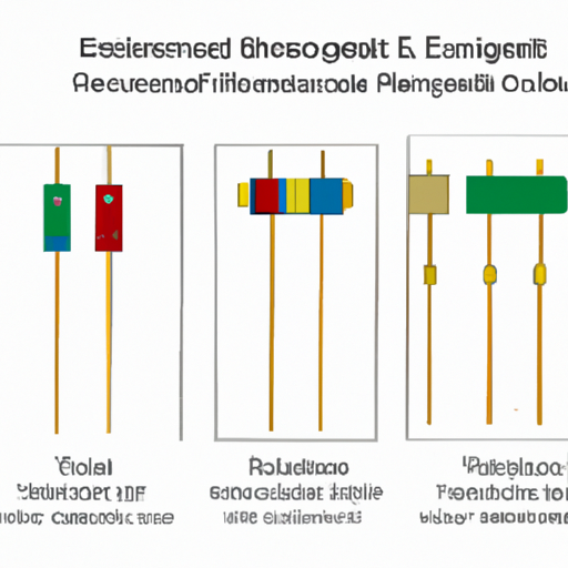
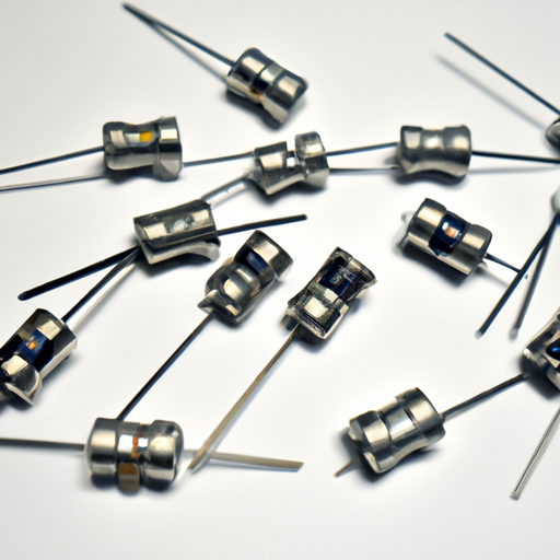
1. **Fixed Resistors**: These resistors have a constant resistance value and are the most commonly used type. They come in various resistance values and power ratings, making them suitable for a wide range of applications.
2. **Variable Resistors (Potentiometers)**: These resistors allow for adjustable resistance values. They are often used in applications like volume controls in audio equipment, where the user can change the resistance to adjust the output.
3. **Specialty Resistors**: These include thermistors (temperature-sensitive resistors) and photoresistors (light-sensitive resistors). They are used in specific applications where resistance changes with environmental conditions.
C. Key Specifications
1. **Resistance Value (Ohms)**: This is the measure of how much a resistor resists current flow. It is denoted in ohms (Ω).
2. **Power Rating (Watts)**: This indicates the maximum power a resistor can dissipate without being damaged. It is crucial to select a resistor with an appropriate power rating for your application.
3. **Tolerance**: This specification indicates how much the actual resistance can vary from the stated value. For example, a resistor with a tolerance of ±5% can have a resistance value that is 5% higher or lower than its nominal value.
4. **Temperature Coefficient**: This indicates how much the resistance changes with temperature. It is important in applications where temperature fluctuations are expected.
III. How to Choose Resistors
A. Determining the Required Resistance Value
1. **Ohm's Law (V = IR)**: This fundamental principle relates voltage (V), current (I), and resistance (R). By rearranging the formula, you can calculate the required resistance for your circuit.
2. **Series and Parallel Resistor Calculations**: When resistors are connected in series, their total resistance is the sum of their individual resistances. In parallel, the total resistance can be calculated using the formula:
\[
\frac{1}{R_{total}} = \frac{1}{R_1} + \frac{1}{R_2} + \ldots
\]
B. Selecting the Appropriate Power Rating
1. **Calculating Power Dissipation**: Use the formulas \(P = I^2R\) or \(P = \frac{V^2}{R}\) to determine how much power a resistor will dissipate in your circuit.
2. **Importance of Headroom in Power Ratings**: Always choose a resistor with a power rating higher than the calculated dissipation to ensure reliability and prevent overheating.
C. Considering Tolerance and Temperature Coefficient
1. **Impact on Circuit Performance**: The tolerance of a resistor can affect the accuracy of your circuit. For precision applications, select resistors with lower tolerance values.
2. **Choosing the Right Tolerance for the Application**: For general applications, a tolerance of ±5% is often sufficient, but for sensitive circuits, consider using resistors with ±1% or ±0.1% tolerance.
IV. Wiring Off-the-Shelf Resistors
A. Tools and Materials Needed
1. **Soldering Iron and Solder**: Essential for making permanent connections in your circuit.
2. **Wire Cutters and Strippers**: Useful for preparing leads and connecting resistors.
3. **Breadboard or PCB (Printed Circuit Board)**: A breadboard is ideal for prototyping, while a PCB is used for permanent installations.
B. Basic Wiring Techniques
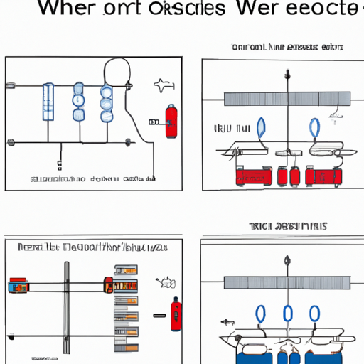
1. **Series Wiring**:
- **Explanation and Diagram**: In series wiring, resistors are connected end-to-end, and the total resistance is the sum of the individual resistances.
- **Applications and Examples**: Series wiring is commonly used in voltage divider circuits.
2. **Parallel Wiring**:
- **Explanation and Diagram**: In parallel wiring, resistors are connected across the same two points, and the total resistance is less than the smallest individual resistor.
- **Applications and Examples**: Parallel wiring is often used in current-limiting applications.
C. Soldering Techniques
1. **Preparing the Resistor Leads**: Trim the leads to the appropriate length and strip any insulation if necessary.
2. **Proper Soldering Methods**: Heat the joint with the soldering iron, then apply solder to create a strong electrical connection.
3. **Ensuring Good Electrical Connections**: Inspect solder joints for cold soldering (dull or cracked) and rework if necessary.
V. Common Mistakes to Avoid
1. **Choosing the Wrong Resistance Value**: Always double-check calculations to ensure the correct resistance is selected.
2. **Underestimating Power Ratings**: Ensure that the power rating of the resistor exceeds the calculated dissipation to avoid failure.
3. **Poor Soldering Techniques Leading to Circuit Failure**: Practice good soldering techniques to ensure reliable connections.
4. **Ignoring Tolerance and Temperature Effects**: Consider the impact of tolerance and temperature on circuit performance, especially in sensitive applications.
VI. Practical Applications of Resistors
1. **Use in Voltage Dividers**: Resistors can be used to create voltage dividers, allowing you to obtain a specific voltage from a higher voltage source.
2. **Current Limiting in LED Circuits**: Resistors are essential for limiting current to LEDs, preventing them from burning out.
3. **Pull-Up and Pull-Down Resistors in Digital Circuits**: These resistors ensure that inputs to digital circuits are at a defined logic level.
4. **Signal Conditioning in Analog Circuits**: Resistors can be used in filters and amplifiers to condition signals for further processing.
VII. Conclusion
In summary, understanding how to choose and wire resistors is vital for anyone working with electronics. Proper selection ensures that your circuits function as intended, while good wiring practices lead to reliable connections. We encourage you to experiment with resistors in your projects, as hands-on experience is the best way to learn. Resistors may be simple components, but they play a significant role in the world of electronics.
VIII. Additional Resources
1. **Recommended Books and Websites for Further Learning**: Look for books on basic electronics and online resources that provide tutorials and guides.
2. **Online Calculators for Resistor Values and Power Ratings**: Utilize online tools to assist in calculating resistor values and power ratings.
3. **Community Forums and Groups for Electronics Enthusiasts**: Join forums and online communities to share knowledge, ask questions, and learn from others in the field.
By following the guidelines outlined in this article, you can confidently select and wire resistors for your electronic projects, enhancing your understanding and skills in the fascinating world of electronics.

