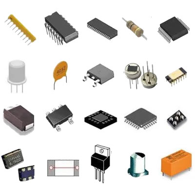
Resistor symbol components similar recommendations
Resistor Symbol Components: Similar Recommendations
I. Introduction
In the world of electronics, resistors play a crucial role in controlling the flow of electric current within circuits. They are fundamental components that help manage voltage levels, protect sensitive devices, and ensure that circuits function as intended. Understanding resistor symbols is essential for anyone involved in electrical engineering, circuit design, or even hobbyist electronics. This article aims to explore the various resistor symbols, their meanings, and similar components that share functional characteristics, providing a comprehensive guide for both beginners and seasoned professionals.
II. Understanding Resistor Symbols
A. Standard Resistor Symbol in Electrical Schematics
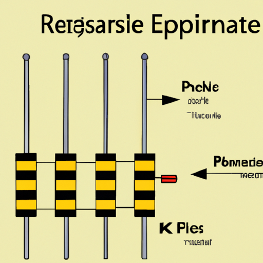
The standard symbol for a resistor in electrical schematics is a zigzag line. This symbol is universally recognized and serves as a visual representation of the resistor's function in a circuit. The zigzag pattern indicates that the component resists the flow of current, converting electrical energy into heat.
B. Variations in Resistor Symbols
While the standard symbol is widely used, there are variations that represent different types of resistors. For instance, a variable resistor, which allows for adjustable resistance, is often depicted as a similar zigzag line with an arrow crossing it. Potentiometers, a specific type of variable resistor, have a more complex symbol that includes a wiper arm, indicating the adjustable nature of the component.
C. Importance of Resistor Symbols in Circuit Design and Analysis
Resistor symbols are not just arbitrary designs; they are essential for effective communication among engineers and technicians. Accurate representation of components in schematics allows for easier understanding, troubleshooting, and maintenance of electrical systems. Misinterpretation of symbols can lead to circuit failures or inefficient designs, highlighting the importance of mastering these symbols.
III. Types of Resistors
A. Fixed Resistors
1. Definition and Characteristics
Fixed resistors are the most common type of resistors, characterized by a constant resistance value. They are typically made from materials like carbon, metal film, or wire wound, and their resistance is determined during manufacturing.
2. Common Applications
Fixed resistors are used in a variety of applications, including voltage dividers, current limiters, and pull-up or pull-down configurations in digital circuits. They are essential in ensuring that circuits operate within safe voltage and current levels.
B. Variable Resistors
1. Definition and Characteristics
Variable resistors allow for the adjustment of resistance values, making them versatile components in circuit design. They can be manually adjusted or controlled electronically.
2. Types: Potentiometers, Rheostats
Potentiometers: These are three-terminal devices used to adjust voltage levels in a circuit. They are commonly found in volume controls for audio equipment and in various control applications.
Rheostats: A type of variable resistor with two terminals, rheostats are used to control current flow in a circuit. They are often employed in applications requiring high power, such as in light dimmers.
3. Applications in Circuits
Variable resistors are crucial in applications where fine-tuning of resistance is necessary. They are used in audio equipment, sensor calibration, and in circuits requiring adjustable speed or brightness.
C. Specialty Resistors
1. Thermistors
Thermistors are temperature-sensitive resistors that change resistance with temperature variations. They are widely used in temperature sensing and control applications, such as in thermostats and temperature compensation circuits.
2. Photoresistors
Photoresistors, or light-dependent resistors (LDRs), change resistance based on light exposure. They are commonly used in light-sensing applications, such as automatic streetlights and camera exposure controls.
3. Other Types and Their Uses
Other specialty resistors include varistors, which protect circuits from voltage spikes, and magnetoresistors, which change resistance in response to magnetic fields. Each type serves specific functions in various electronic applications.
IV. Similar Components to Resistors
While resistors are vital components in circuits, several other components share similar characteristics or functions. Understanding these components can enhance circuit design and analysis.
A. Capacitors
1. Definition and Function
Capacitors store and release electrical energy in a circuit. They are essential for filtering, timing, and energy storage applications.
2. Symbol and Variations
The standard symbol for a capacitor is two parallel lines, with variations indicating different types, such as polarized capacitors.
3. Applications in Circuits
Capacitors are used in power supply circuits, audio equipment, and timing circuits, playing a crucial role in smoothing out voltage fluctuations and storing energy.
B. Inductors
1. Definition and Function
Inductors store energy in a magnetic field when current flows through them. They are used in applications involving alternating current (AC) and are essential for filtering and energy storage.
2. Symbol and Variations
The symbol for an inductor consists of a series of loops or coils, with variations indicating different types, such as toroidal inductors.
3. Applications in Circuits
Inductors are commonly found in power supplies, radio frequency applications, and in circuits requiring energy storage and filtering.
C. Diodes
1. Definition and Function
Diodes are semiconductor devices that allow current to flow in one direction only. They are crucial for rectification and signal modulation.
2. Symbol and Variations
The symbol for a diode is a triangle pointing to a line, with variations for different types, such as Zener diodes and Schottky diodes.
3. Applications in Circuits
Diodes are used in power supply circuits, signal processing, and protection circuits, ensuring that current flows in the desired direction.
D. Transistors
1. Definition and Function
Transistors are semiconductor devices used for amplification and switching. They are fundamental building blocks of modern electronic devices.
2. Symbol and Variations
The symbol for a transistor varies based on its type (NPN or PNP), with distinct representations for each.
3. Applications in Circuits
Transistors are used in amplifiers, digital circuits, and as switches in various applications, making them essential for modern electronics.
V. Importance of Component Symbols in Circuit Design
A. Communication Among Engineers and Technicians
Accurate representation of components through symbols facilitates clear communication among engineers and technicians. It ensures that everyone involved in a project understands the design and functionality of the circuit.
B. Standardization in Electrical Schematics
Standardized symbols help maintain consistency in electrical schematics, making it easier to read and interpret designs. This standardization is crucial for collaboration and documentation.
C. Role in Troubleshooting and Maintenance
Understanding component symbols is vital for troubleshooting and maintaining electrical systems. Technicians can quickly identify components and their functions, leading to more efficient repairs and modifications.
VI. Conclusion
In conclusion, understanding resistor symbols and similar components is essential for anyone involved in electrical engineering or circuit design. Resistors, with their various types and functions, play a critical role in managing current and voltage in circuits. Additionally, recognizing similar components such as capacitors, inductors, diodes, and transistors enhances one's ability to design and analyze complex electrical systems.
As technology continues to evolve, the importance of mastering these symbols and components will only grow. We encourage readers to further explore the fascinating world of electrical components, as a deeper understanding can lead to innovative designs and solutions in the field of electronics.
VII. References
- "The Art of Electronics" by Paul Horowitz and Winfield Hill
- "Electrical Engineering 101" by Darren Ashby
- IEEE (Institute of Electrical and Electronics Engineers) website
- Electronics tutorials and resources from educational websites like Khan Academy and Coursera
By delving into the intricacies of resistor symbols and their related components, we can appreciate the complexity and beauty of electrical engineering, paving the way for future innovations and advancements in technology.

