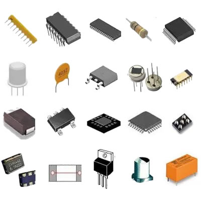
What are the mainstream models of resistor wiring?
What are the Mainstream Models of Resistor Wiring?
I. Introduction
Resistors are fundamental components in electronic circuits, serving as the building blocks for controlling current flow and voltage levels. They are essential for a wide range of applications, from simple devices to complex electronic systems. Understanding how resistors are wired in circuits is crucial for anyone involved in electronics, whether you're a hobbyist, student, or professional engineer. This article will explore the mainstream models of resistor wiring, including series, parallel, and series-parallel configurations, along with their applications, advantages, and troubleshooting techniques.
II. Basic Concepts of Resistor Wiring
A. What is a Resistor?
A resistor is a passive electrical component that limits the flow of electric current in a circuit. Its primary function is to provide a specific amount of resistance, measured in ohms (Ω), which helps control voltage and current levels. Resistors come in various types, including fixed, variable, and specialty resistors, each designed for specific applications.
B. Electrical Principles
1. Ohm’s Law
Ohm’s Law is a fundamental principle in electronics that relates voltage (V), current (I), and resistance (R) in a circuit. It states that the current flowing through a conductor between two points is directly proportional to the voltage across the two points and inversely proportional to the resistance. The formula is expressed as:
\[ V = I \times R \]
This relationship is crucial for understanding how resistors function in different wiring configurations.
2. Voltage, Current, and Resistance
In any electrical circuit, voltage is the potential difference that drives current through the circuit, while resistance opposes the flow of current. The interplay between these three elements is essential for designing effective circuits and understanding how different resistor wiring models impact circuit behavior.
III. Mainstream Models of Resistor Wiring
A. Series Wiring
1. Definition and Characteristics
In a series wiring configuration, resistors are connected end-to-end, forming a single path for current to flow. The total resistance in a series circuit is the sum of the individual resistances:
\[ R_{total} = R_1 + R_2 + R_3 + ... + R_n \]
2. Voltage and Current Distribution
In a series circuit, the same current flows through each resistor, but the voltage across each resistor can vary. The total voltage across the series circuit is equal to the sum of the voltages across each resistor:
\[ V_{total} = V_1 + V_2 + V_3 + ... + V_n \]
3. Advantages and Disadvantages
**Advantages:**
- Simple to design and implement.
- Easy to calculate total resistance and voltage drops.
**Disadvantages:**
- If one resistor fails (opens), the entire circuit is interrupted.
- Voltage drop across each resistor can lead to significant power loss.
B. Parallel Wiring
1. Definition and Characteristics
In a parallel wiring configuration, resistors are connected across the same two points, creating multiple paths for current to flow. The total resistance in a parallel circuit is calculated using the formula:
\[ \frac{1}{R_{total}} = \frac{1}{R_1} + \frac{1}{R_2} + \frac{1}{R_3} + ... + \frac{1}{R_n} \]
2. Voltage and Current Distribution
In a parallel circuit, the voltage across each resistor is the same, while the total current is the sum of the currents through each resistor:
\[ I_{total} = I_1 + I_2 + I_3 + ... + I_n \]
3. Advantages and Disadvantages
**Advantages:**
- If one resistor fails, the circuit remains operational.
- Provides multiple paths for current, which can improve reliability.
**Disadvantages:**
- More complex to calculate total resistance and current distribution.
- Can lead to higher total current, which may require larger power supplies.
C. Series-Parallel Wiring
1. Definition and Characteristics
Series-parallel wiring combines both series and parallel configurations, allowing for more complex circuit designs. This model is often used in applications where specific voltage and current requirements must be met.
2. Applications in Complex Circuits
Series-parallel configurations are commonly found in complex electronic devices, such as audio equipment, where different components require varying voltage and current levels.
3. Advantages and Disadvantages
**Advantages:**
- Flexibility in designing circuits to meet specific requirements.
- Can optimize performance by balancing voltage and current distribution.
**Disadvantages:**
- More complex to analyze and troubleshoot.
- Requires careful planning to avoid misconfigurations.
IV. Practical Applications of Resistor Wiring Models
A. Series Wiring Applications
1. Simple Circuit Designs
Series wiring is often used in simple circuits, such as LED circuits, where a single path for current is sufficient. This configuration is easy to implement and understand.
2. Voltage Divider Circuits
Series resistors can be used to create voltage dividers, which provide a specific output voltage from a higher input voltage. This is useful in applications where a lower voltage is needed for specific components.
B. Parallel Wiring Applications
1. Load Balancing
Parallel wiring is commonly used in load balancing applications, such as in power distribution systems, where multiple devices share the same voltage source.
2. Power Distribution
In power distribution networks, parallel configurations ensure that power is evenly distributed among various loads, improving efficiency and reliability.
C. Series-Parallel Applications
1. Complex Electronic Devices
Series-parallel configurations are prevalent in complex electronic devices, such as computers and smartphones, where different components require specific voltage and current levels.
2. Audio Equipment and Amplifiers
In audio equipment, series-parallel wiring is used to optimize sound quality and performance by balancing the load across multiple speakers and amplifiers.
V. Factors Influencing Resistor Wiring Choices
A. Circuit Requirements
1. Desired Resistance Values
The required resistance values for a circuit will significantly influence the choice of wiring configuration. Series wiring is suitable for higher resistance needs, while parallel wiring is ideal for lower resistance.
2. Power Ratings
Power ratings of resistors must also be considered, as different configurations can lead to varying power dissipation across components.
B. Component Availability
The availability of specific resistor types and values can impact the choice of wiring configuration. Designers may need to adapt their plans based on what components are readily available.
C. Cost Considerations
Cost is always a factor in circuit design. Series configurations may be less expensive due to fewer components, while parallel configurations may require more resistors, increasing costs.
D. Space and Layout Constraints
Physical space and layout constraints can also dictate wiring choices. Series wiring typically requires less space, while parallel wiring may need more room for multiple components.
VI. Troubleshooting Common Resistor Wiring Issues
A. Identifying Series and Parallel Misconfigurations
Misconfigurations can lead to circuit failures. Understanding the characteristics of series and parallel wiring is essential for identifying and correcting these issues.
B. Measuring Resistance and Voltage Drops
Using a multimeter to measure resistance and voltage drops across resistors can help diagnose problems in a circuit. This is crucial for ensuring that the circuit operates as intended.
C. Common Faults and Solutions
Common faults include open circuits, short circuits, and incorrect resistor values. Solutions may involve replacing faulty components, reconfiguring the circuit, or recalculating resistance values.
VII. Conclusion
Understanding the mainstream models of resistor wiring—series, parallel, and series-parallel—is essential for anyone working with electronic circuits. Each configuration has its advantages and disadvantages, making it crucial to choose the right model based on specific circuit requirements. As technology advances, new trends in resistor technology and wiring techniques will continue to emerge, further enhancing the capabilities of electronic devices. By mastering these concepts, you can design and troubleshoot circuits more effectively, paving the way for innovation in the field of electronics.
VIII. References
A. Suggested Reading Materials
- "The Art of Electronics" by Paul Horowitz and Winfield Hill
- "Electronics for Dummies" by Cathleen Shamieh
B. Online Resources and Tutorials
- Khan Academy: Electrical Engineering
- All About Circuits: Resistor Basics
C. Relevant Standards and Guidelines
- IEEE Standards for Electrical and Electronic Equipment
- IEC Standards for Resistors and Resistor Networks
This comprehensive overview of resistor wiring models provides a solid foundation for understanding how resistors function in electronic circuits. Whether you're designing a simple circuit or troubleshooting a complex system, the knowledge of these wiring configurations will serve you well in your electronic endeavors.

